It’s time to add the cylinders.
This is the top of the front cylinder, with the old head gasket removed.
We know this is the front cylinder because the cam chain tensioner (lower right) is always installed towards the rear, and only the rear cam chain is on the right side. To reduce silly errors, we’ve also marked this cylinder with an ‘F’ (for front), and marked forwards-pointing arrows on both the cylinder and piston top. Because the piston tops are also cast with a ‘EX’ mark near the exhaust, we can also identify the front and rear pistons.
Cylinders, pistons and rings wear together. Returning these parts to their original positions tends to avoid excessive wear and a subsequent increase in oil consumption.

The old base gasket is still on the bottom of the front cylinder.
The wrist pin is a push-fit in its piston, and remains at the position used to separate the pin from its rod.

We’ve removed the old base gasket and cleaned the cylinder’s crankcase mating surface.

We’ve added a new O-ring around the cylinder skirt.

The new base gaskets are a pleasing turquoise colour.

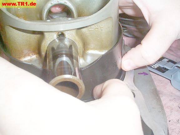
We’ll lower the front cylinder with its piston onto its studs just far enough to fasten the piston pin onto its rod.

We’ve pushed the wrist pin through the rod and piston.
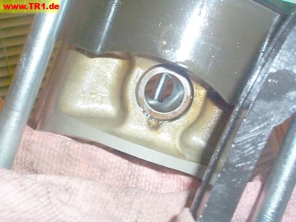
The magical wrist pin attractor force eminating from the depths of the crankcase has been blocked by a shop rag.
(We never did find the original piston pin clip that flew off as it was being removed.)

A wrist pin clip.
Yamaha recommends that these clips not be reused. This is a moot point if the original achieves escape velocity during removal.
There are wrist pin clips at both ends of the wrist pin, but it’s only necessary to disturb the clip nearer the cam chain in order to slide the wrist pin out of its rod.

We had no difficulty installing a new wrist pin clip using a large pair of needle-nose pliers. We covered the seated portion of the wrist clip with a thumb as we compressed and worked each section of clip into the round piston pin hole. After the entire clip was worked into its hole, the clip was shoved against the pin, seating into its groove with an audible click.
Some manuals recommend the clip’s ends be positioned away from the removal slot, but our Yamaha manual makes no mention of this.

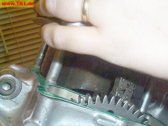
We’ve transferred the gasket onto the crankcase dowels.
One of the two dowels is visible, just to the right of the right cam chain.

The cylinder locating dowels are engaged.

The front cylinder is seated on the crankcase.

Now, we’ll repeat the installation procedure for the rear cylinder.
Here’s the top of the rear cylinder.
We know this is the rear cylinder because we know the adjuster faces rearwards, and the rear cam chain is on the left. Of course, this is the only remaining cylinder. ;-)

We’ll peel and scrape the remainder of the old base gasket from the bottom of the cylinder.

A new O-ring is pushed into the groove in the base of the cylinder sleeve (just visible; between thumbs).

We’ve added a new turquoise cylinder base gasket and black O-ring.

We’ll run our scraper around the mating surface one last time, just before putting on the cylinder.

The rear cylinder base has been cleaned.
Both piston rods are visible between the crankshaft counterweights.

Just for grins, we’ll squirt some oil on the crankcase bearings before we put the rear cylinder on.
Since we’ll also tip the engine onto either side after completely reassembling it and adding oil, this isn’t really necessary.

We’ve pushed the wrist pin through the end of the rod, and we’re ready to add a new wrist pin clip to the rear piston.
As we’re about to add the wrist pin clip, we’ve covered the dark and twisty passages of the crankcase with a shop rag.

The wrist pin clip was inserted into its slot without difficulty or surprises.

The rear cylinder has been pushed closer towards the crankcase.

We’ve transferred the base gasket onto the locating dowels on the crankcase.

The bottom of the cylinder has to be guided past the crankcase opening.
Here, the bottom of the cylinder would hit the front of the crankcase.

The bottom of the cylinder has to be guided past the crankcase opening.
Here, the bottom of the cylinder would hit the rear of the crankcase.

Both cylinders are seated.
The cam chains are temporarily held up by rubber bands.
We’ll add the three bolts that help secure each cylinder base to the crankcase when we’re ready to torque the heads to the cylinder studs.
This is starting to look more like an engine. :-)
