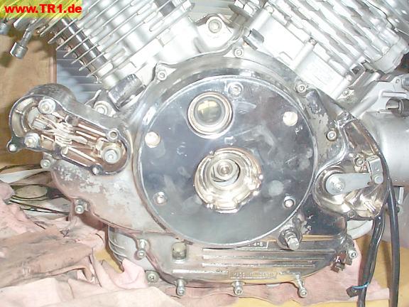
We’re ready to install the left side cover.
The two crankshaft position sensors (pictured about 11 o’clock and 2 o’clock) sit outside the flywheel.
They signal when to fire each spark plug.
The 18 alternator stator coils (pictured below the two position sensors) are positioned inside the middle of the flywheel/rotor. The alternator rotor includes 6 permanent magnets (6 north poles, and 6 south poles).
As the alternator rotor spins, each of the 12 (north/south) permanent magnet poles generates an alternating (positive/negative) current in the coils.(A changing magnetic field moves electrons in a conductor.)
The alternating current is rectified (by 6 diodes – also known as rectifiers) and voltage-regulated (to about 14.5 volts) in the rectifier/regulator assembly (located behind the left passenger foot peg), to keep the battery charged.

Here’s a better view of one of the ignition (timing) pickup coils.

Wires to the alternator stator and crankshaft position sensors travel through this rubber plug.
These three alternator stator wires (seal bottom) and ignition pickup wires (seal right) exit the engine (seal top-left) through this rubber plug.
The 18 alternator stator coils are wired in a (series? parallel? both?) ‘Y’ configuration, with six coils per each of the three legs of the ‘Y’, so only three wires connect the stator coil assembly to its rectifier/regulator assembly (located behind the left passenger foot peg).
Each of the three stator wires goes to a pair of diodes: one diode’s cathode and another diode’s anode. The remaining three anodes are connected to the battery’s negative terminal, while the remaining three cathodes go to the battery’s positive terminal, perhaps through the voltage regulator.
If the engine is run with a weak or disconnected battery, one or more of the three diodes (rectifiers) in the rectifier/regulator assembly may fail.
It’s usually possible to substitute a full-wave rectifier in place of one or two pairs of failed diodes. Radio Shack sells a suitable full-wave (four-diode) rectifier for $5 – much cheaper than Yamaha – but that’s another story.
The clutch push rod thing is at the bottom left.

The clutch push rod mechanism.
When the clutch lever is applied, the plate and button are pushed towards the clutch by the internal worm threads. The button pushes against the long push rod, which pushes the short push rod, which pushes against the clutch basket cover, unclamping the clutch/friction disks, which disconnects the engine from the transmission.

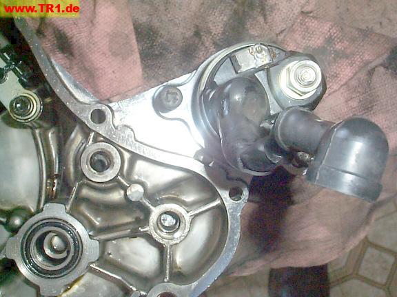
The starter solenoid hangs off of the top front end of sidecover.
The large exposed stud with the nut (top right) will be connected to the battery.
The smaller push-on terminal (top) will be connected to to the starter button.
The large black cable will be connected to the start motor. (Poor picture – sorry.)
The starter motor shaft hole is at 7 o’clock, and the starter fork shaft hole is at 8 o’clock, with respect to the solenoid.
The large metal/rubber/metal bushing for the starter gear shaft is at the extreme lower-left.

We’re ready to install the left sidecover gasket.

The left sidecover gasket is being held in place by its two locating dowels and a thin film of oil.

We’ve added the left sidecover and its bolts.
Since these bolt lengths vary, we’ll first match the bolts to the appropriate holes by checking their exposed lengths.

We’ll finger-tighten the bolts before torqueing ‘em.

The starter fork shaft bolt is torqued to its rod; this bolt has a torx head.
Yeah, we might have overdone it with the water-resistant white grease. ;-)

The shifter shaft is at the top right.
The shift pattern (1-N-2-3-4-5) is in the middle.
The oil level window is to the left.
