Now, we’ll install and time the rear head.
The rear head is still grubby.
The exhaust studs and valve are to the left; the intake valve and carb coller are to the right.
The camshaft sprocket is visible below the valves.
The anti-smog fitting is visible below the exhaust studs (bottom left).

The old head gasket is removed with light pressure.

The new head gasket will require a clean, smooth surface free of scratches.
We carefully pushed the scraper around the head/cylinder mating surface to remove most traces of the old head gasket, and a flat-blade screwdriver to carefully remove most of the carbon from the curvy valve area.

Looks good.
One of the dowels near the exhaust valve (top left) doesn’t want to come out of the head, so we just left it there.

A cylinder head dowel.
Two of these are used to prevent the head and/or gasket from sliding across the top of the cylinder.

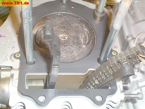
The rear piston has been cleaned of most of its carbon deposits.
The crankshaft and timing gear are set to the timing position for the rear cylinder, so this piston is at TDC (top dead center), just after when the spark plug fires.
The piston’s steel cylinder sleeve is visible as a ring between the piston and studs.
The indentation for the EXhaust valve edge is marked ‘EX’ (bottom).
One of the two locating dowels is already installed. (bottom right)

The two front cam chain guides (one for each cylinder) are held in channels in each head (little end) and crankcase (big end).
These guides are straight, rigid, and are not adjustable.
The camshaft is *pulled* via the forward-facing half-loop of chain by the timing gear; any slack in the rear-facing half-loop of chain is [mostly] removed by the cam chain tensioner.

The rear cam chain guide (right) is hinged at the bottom, and remains locked to the crankcase by a pinch bolt.
We haven’t bothered to disconnect the rear cam chain guides from the crankcase.

We’ve placed the bottom of the front cam guide (left) in its slot in the crankcase.

Now that we’re close to adding the head, we’ll torque the three cylinder base bolts.
Because this hex bit got in the way of the cylinder fins, we retorqued the three bolts with a hex wrench by hand, using an accurately-torqued bolt for an example of the correct torque.
The shop manual indicates these three cylinder base bolts are torqued before the head, so that’s what we’ll do.
Typically, smaller outside bolts are torqued last – but these bolts don’t retain the head.

Each new head gasket is a fiber/metal/fiber sandwich.
These head gaskets are held together by a pair of small external rivets that will protrude outside the head/crankcase area.
The original head gaskets didn’t have rivets (when we removed them).
I have no clue what the small hole (image top) in the head gasket is intended for.

The new head gasket has been added.
Oops.. we’ll move the dowel (top right) to the other hole (bottom right) to allow for the dowel that’s stuck in the head. We’ll even do this before sliding the head onto all its studs. ;-)

The rear head, top view.
The rear exhaust pipe studs are visible to the right.
The missing fins in the upper-left corner provide clearance for the front head’s carb air intake hose.

The rear head from the side.
The right-angle anti-smog fitting (for California engines) is at the bottom right.
Adding some exhaust gas to the intake air (EGR – exhaust gas recirculation) lowers peak cylinder termperatures, NOx (oxides of nitrogen), and lets the engine run a bit better on lower-octane fuel – or so I’ve read.

The head is being guided onto its studs.
We’ll use the wire to pull the cam chain through the opening.

The cam sprocket must be temporarily removed to provide clearance for the chain.

The rear cam sprocket, washer and bolt.
The camshaft dowel fits in the small hole above the large hole for the bolt to keep the camshaft and sprocket positions locked together.

It’s necessary to manually position the head gasket onto the dowel that’s still stuck in the head.

The tip of the front cam chain guide tends to hit on the edge of its hole in the head, preventing the head from completely seating.
We noticed this before thwacking on the head.. very many times. Oh. Oops.

The front cam chain guide (left) must be positioned under its slot as the head is {more carefully} lowered onto its cylinder.

The front cam chain guide stays in its slot once the head is resting on its cylinder.

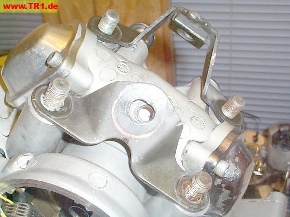
Each head is fastened to its cylinder by four nuts, one cap nut, and two bolts.
The front cylinder fasteners are to the left.
The rear cylinder fasteners and motor mounts are to the right.

The rear motor mounts are not symmetrical because the rear cylinder is offset slightly to the left of the engine centerline.

The four large head studs protrude past the top of the head.

The rear motor mounts also function as steel washers for the four head stud nuts.
Both of the captive motor mount nuts are visible in the middle of their motor mount hanger brackets.

We’re ready to torque the rear head onto the engine.
First, the large head nuts are torqued in a diagonal order.

The motor mount hanger bracket tops point inwards, which makes it easier to align the frame-to-hanger bolts to their nuts when the engine is jacked upwards into the frame.
We’ll torque the cylinder head cap nut (between the two studs at the right) next.

The cap nut by the spark plug hole is being torqued.

Finally, we’ll torque the two bolts on the left side of the rear cylinder, by the cam chain.
This completes torqueing of the rear head.

We’ve already timed the rear timing gear to the crankshaft, but we’ll just confirm this with a quick idiot check before continuing to time the rear camshaft.
Because it’s not quite possible to view the timing gear mark through the timing hole while the gears are meshed, we verified that our timing gear timing was correct like this:
Yay! The gear is still timed properly.
The front head is not yet installed, so the front-to-rear timing is not yet relevant,
To time the rear camshaft, we’ve positioned the rear piston at TDC, and aligned its timing gear mark with the flywheel/alternator timing hole.

With the rear piston at TDC, we slid the sprocket inside the chain and onto the camshaft so that the sprocket timing mark pointed (almost) to the ‘V’ mark (top center of head) while the slop was temporarily taken out of the rear half of the chain.
We took the slop out of the cam chain by pushing on the rear cam chain tensioner through the tensioner hole with a finger.
Because this sprocket turns counter-clockwise, the sprocket timing dot is slightly less than one-half-sprocket retarded (late; too far clockwise; to the right). Googling suggests that this is typical. This is also what would be expected because chains lengthen slightly as they wear.
If it weren’t such a pain to adjust the timing gear, it might be fun to readjust the timing gear to compensate for the slight chain stretch. Not today.

We’ve torqued the camshaft sprocket bolt to the end of its camshaft.
We prevented the crankshaft (and everything else) from rotating very much by strapping the alternator to the crankcase.
The crankshaft and camshaft moved a little while we were torqueing this bolt, but we didn’t reposition the crankshaft at its mark before taking this picture, so this image shows the timing mark a half-tooth off.

The cam chain tensioner tries to take most of the slop out of the cam chain by pushing the rear cam guide against the rear half of the chain.
This tensioner plunger is fully extended.
The little rubber dust plug normally covers the adjuster’s screw hole (bottom).

Here’s how the tensioner plunger looks after being wound to its minimum extended position, ready for installation in the side of the cylinder.

The tensioner plunger is retracted for installation by turning the screw clockwise while pushing the plunger into the tensioner body.
The manual suggests one can prevent the tensioner screw from unwinding by inserting a flat strip of metal through the slot, but both our tensioners tended to stay wound up until the screw was pushed slightly – or until we dropped one on the table. ;-)

We’ve added a new tensioner gasket, bolted the tensioner to the head, and pushed on the tensioner screw to extend the plunger. The rear cam chain is now tensioned.

Just to see how much tensioner travel was available, we evenly loosened both bolts until the rear cam chain guide was no longer under tension. Note the gap between the tensioner and cylinder – this looks reasonable.
After performing this test, we *again* had to remove, wind, reinstall, and push on the rear screw to re-activate the tensioner. Bad Things would happen if we had simply retightened the hex bolts without first winding up the tensioner screw, because the tensioner needs help to retract.
The proper procedure to determine excessive chain stretch is to measure the distance between the center of both sprockets while the chain is under tension and out of the engine.
We’re done with the rear cylinder for now.
