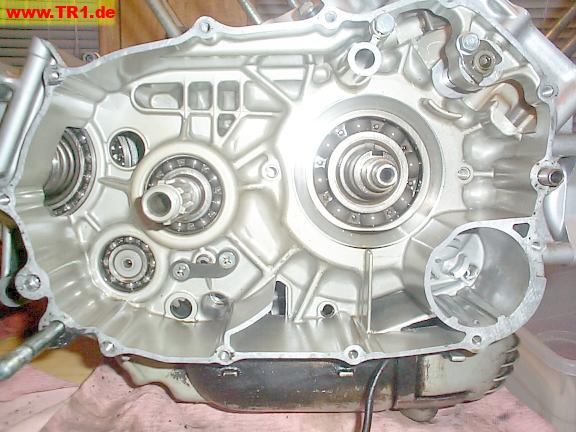
The empty right side.
There’s nothing much here but the transmission mainshaft (left), crankshaft (right), and oil filter housing (bottom right).
We’ll add the primary gear, clutch, and timing gears for the front cylinder.
These bearings get oiled by splash.
While this might be a good time to squirt some oil onto these bearings before installing parts over them, we just flipped the engine onto each of the two sidecovers after the engine was assembled and oil was added.
YMMV (your mileage may vary).
The primary gear assembly has to go on before the other stuff on this side.
The primary gear assembly slipped right on the crankshaft, and the rectangular locking key (visible) slipped right into its slot between the crankshaft and primary gear.
The key fits in slots cut into the crankshaft and primary gear hub, locking the primary gear at this position on the crankshaft.
The primary gear assembly consists of the primary gear and timing drive gear.
The primary gear (the larger gear) is directly keyed to the crankshaft, and will drive the clutch.
The timing gear (the smaller gear) is anchored to the primary gear by strong springs, and will drive the front cylinder timing gear – camshaft chain – camshaft – valve train. The springs tend to absorb abrupt jerks to the front cylinder’s valve train.
These gears felt like they would prefer to remain assembled, so we didn’t try prying them apart for educational purposes.
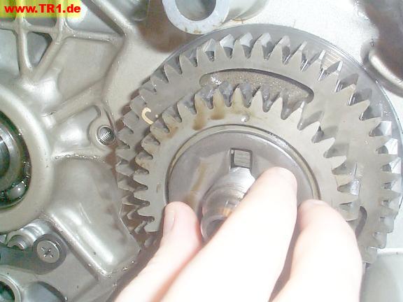
The locking washer has been added; the tabs will be bent around the nut to prevent it from loosening.
A short right-angle anchor tab at the bottom of the locking washer (just visible under the crankshaft end) fits into the gear hub to prevent the plate from turning around the crankshaft.
Yamaha recommends buying a new locking plate. Based upon this plate’s apparent condition, we’ll reuse it. YMMV.
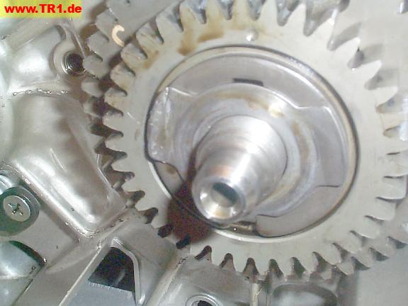
The primary gear nut is finger-tight on the crankshaft.
We’ll torque and lock it when we can more easily prevent the crankshaft from turning.
The clutch housing (outer basket) and clutch boss (inner basket) live on the transmission mainshaft.

The bushing (partially visible) allows the clutch outer basket to rotate freely on the mainshaft.
The bushing is grooved to channel pressurized oil from the hollow mainshaft.
The ring gear will mesh with the crankshaft primary gear.
The springs tend to even out the torque impulses between the ring gear and the clutch outer basket.
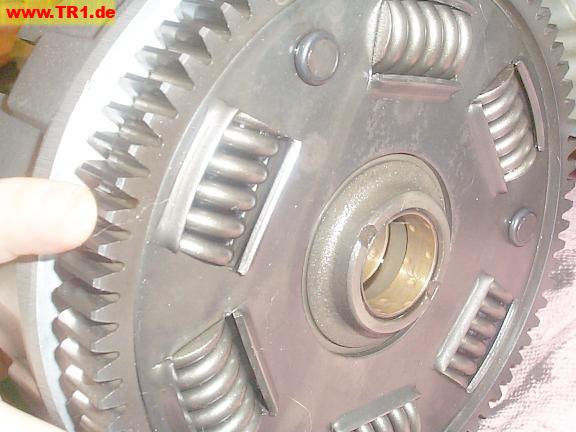
The clutch outer basket is seated on the smooth surface of the mainshaft, meshing with the primary gear.
Some engines use a primary *chain* rather than a primary gear.
Chains generally require less space but introduce more slop.
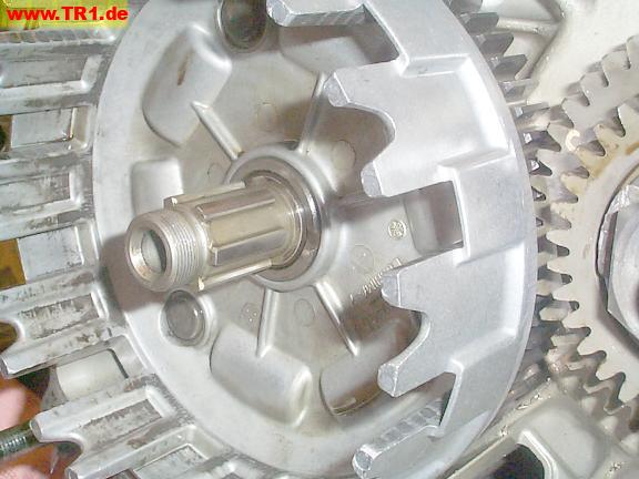
The raised mainshaft shoulder to the right of the mainshaft splines will
prevent the thrust washer from pushing on the outer clutch basket.
Next, we’ll install the thrust washer.

The clutch thrust washer has been seated against the mainshaft shoulder.
The clutch thrust washer will be held tight against the mainshaft shoulder by the inner basket and mainshaft nut.

The back of the clutch boss (inner basket).
These splines mate with the transmission mainshaft.
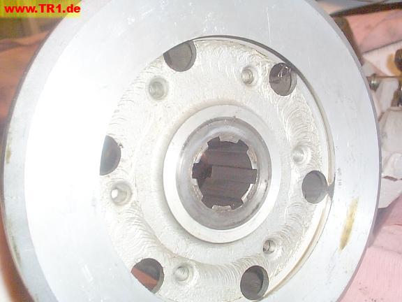
The clutch boss (inner basket) has been slid onto the mainshaft splines, and against the thrust washer.

We’ve added the clutch boss locking washer and screwed the nut finger-tight.
The strap will prevent the clutch boss from rotating when we torque the nut.
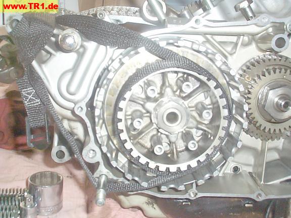
The clutch boss nut has been torqued and locked down.
The anchoring tab (about 10 o’clock from the nut) prevents the locking washer from turning.
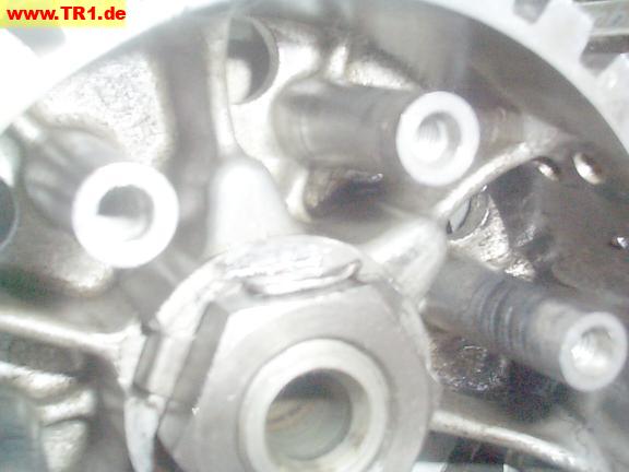
We’ll now add alternating friction discs and clutch plates.
The metal clutch plate slots/tabs mate with the clutch boss (inner basket).
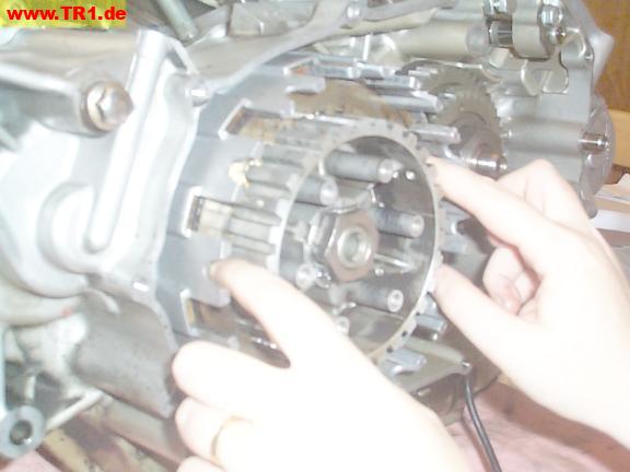
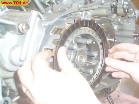
The friction disc slots/tabs mate with the clutch housing (outer basket).
The long clutch pushrod, short pushrod, thrust bearing and washer function to disengage the clutch.
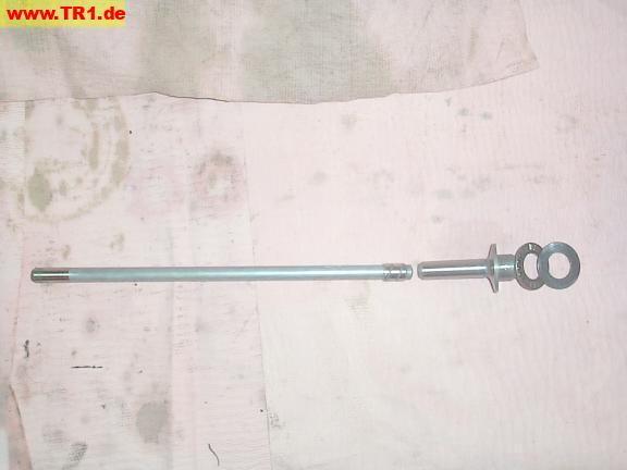
The small end of the long pushrod is chromed to resist wear.
This end will live inside the *left* sidecase cover.
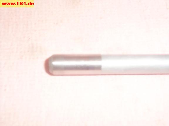
The large end is too wide to fit through the pushrod hole in the *left* crankcase half, so it has to go into the hollow transmission mainshaft from the *right* end. So, we have to add it *before* we install the pressure plate.
::Ahem:: Good judgement comes from experience. Experience comes from BAD judgement. (Author unknown to me.)
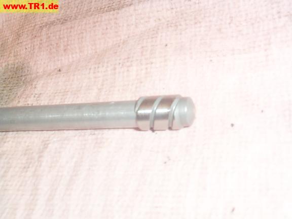
First, we’ll slide the long pushrod into the hollow mainshaft, small end first.
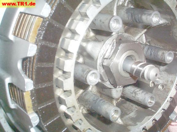
Next, we’ll add the short pushrod, thrust bearing and washer.
We’ll oil the bearing before installation.
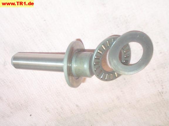
We’ve installed the short pushrod, thrust bearing and washer.
The washer will push against the pressure plate (to follow). The bearing allows the pushrods to remain stationary while the pressure plate rotates.

We’ve added the clutch pressure plate and some of the springs and bolts.
The bolts thread into the clutch boss (inner basket).
The springs push the pressure plate and clutch boss together, clamping all the clutch plates and discs between them.
The end of the short pushrod is visible in the center of the pressure plate.
When the clutch handle is pulled to disengage the engine from the transmission, the clutch pushrod pushes the pressure plate outwards, compressing the springs even more, and unclamping the plates/discs.
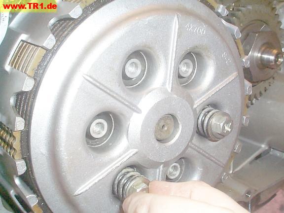
We’re torquing the clutch pressure plate bolts.
The rag, between the clutch ring gear and primary gear, prevents the outer clutch basket (and primary gear) from rotating.
We’re done with the clutch.

Just for grins, let’s check the clutch pushrod from the left case half.
This is as far in (towards the clutch) that the pushrod will go with fingertip pressure.
As the clutch discs wear, more of the pushrod will protrude.

This is as far as the long pushrod can be pulled out from the left case half.
We can’t remove (or install) the pushrod from this side because the bushing on the end is wider than the hole.
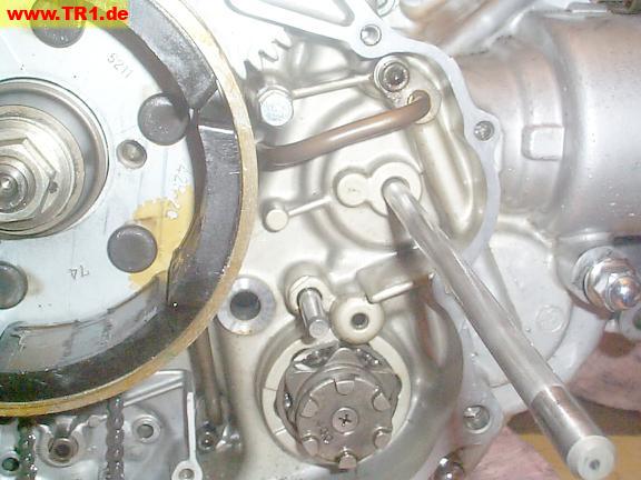
Back to the right-hand sidecase.
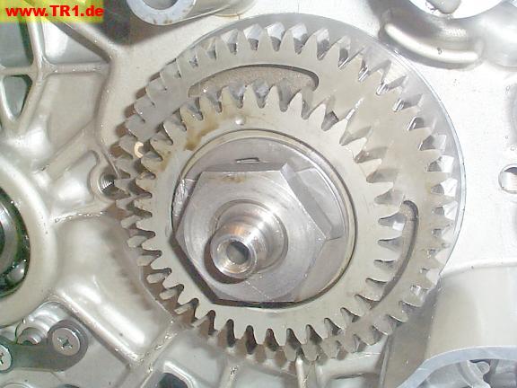
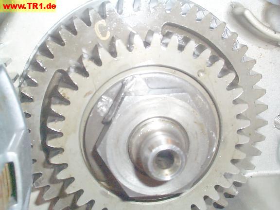
The primary gear is being torqued.
The rag has been relocated to prevent the primary gear from rotating.

Both tabs of the locking washer have been bent around the primary gear nut to prevent it from loosening.
We’re done with the primary gear.
I have no clue what the ‘C’ on the primary gear signifies.
Let’s add the right-side camshaft timing gear and its chain.
This gear will mesh with its drive gear (the [smaller] gear in front of the primary gear) on the crankshaft.
The top end of this chain will rotate the camshaft sprocket in the front head.
The *side* of the chain facing away from the gear when the assembly was removed will be the same as when the assembly is reinstalled. I *think* this will avoid increasing wear and associated slop, but don’t know – so it seems to be the safer choice.
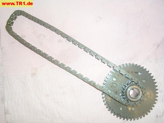
There’s actually two gears here.
Only the darker-colored gear is directly attached to the sprocket.
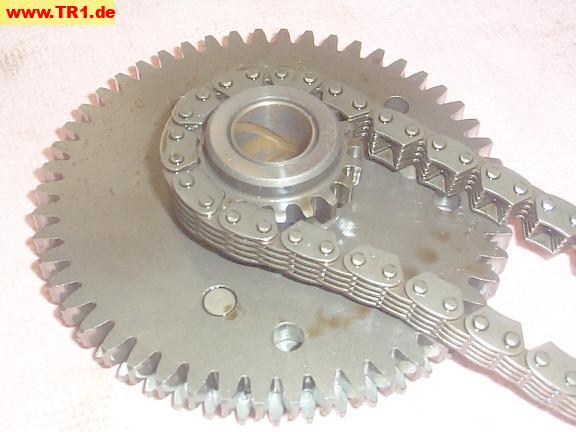
This is the other side of the timing gear assembly.
The lighter-colored anti-lash gear (top gear) is spring-loaded to the gear under it.
The objective of the anti-lash gear is to remove ‘backwards’ slop between the driving and driven gear. The anti-lash gear isn’t directly connected to the sprocket.
This cam gear assembly is for the right side, so the crankshaft turns counter-clockwise (when viewed from the right side), so the timing gear is pushed clockwise, so the anti-lash gear is spring-loaded to move a fraction of a tooth *more* clockwise (to push against the trailing edge of the driving gear). (The left-side anti-lash timing gear turns in the opposite direction, so its springs are also reversed.)

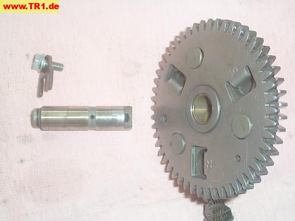
The right timing gear with its shaft, locking collar, and bolt.
Splashed oil from the crankcase travels into the right end of the shaft, and out a pair of oil holes about the middle of the shaft to oil the timing gear bushing.
The left end of the shaft is slotted so the oil intake hole always points up to capture splashed oil.
The right-hand cam gear, almost in position.
Note the misaligned anti-lash alignment hole (upper left) and timing dots (lower left).
The spring-loaded anti-lash gear prevents the gears from meshing.

NOTE:
It appears these timing marks must also be timed to 285 crankshaft degrees after the rear (number one) cylinder timing marks (rear timing gear timing and rear camshaft timing) align.
Since we have nothing better to do, we’ll just align the front [driving and driven] timing gears now, and possibly re-time this gear sometime after the rear camshaft is installed .
We could wiggle the screwdriver in the alignment hole to *almost* – but not quite – get the shaft in.
This probably wouldn’t have been a problem if we had used a suitably short tapered shaft rather than this screwdriver. No problem: we’ll try another method.
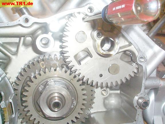
The gears are meshed, the timing dots align, and the timing gear shaft is partially inserted.
We easily meshed the gears by pushing the timing gear from above with a larger screwdriver blade (visible at upper-right) while twisting the blade to align the anti-lash gear with the timing gear.
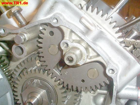
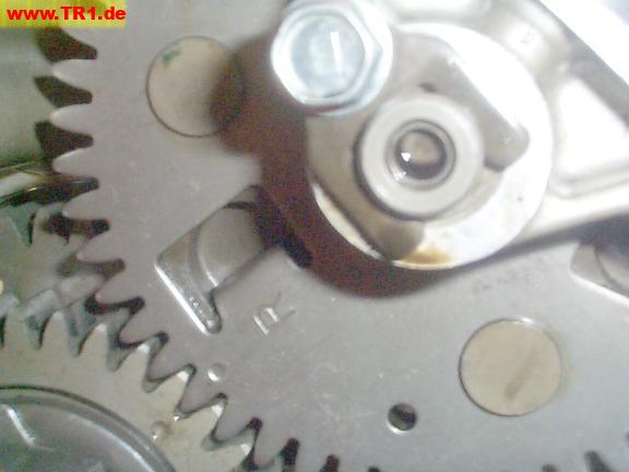
The right-side (front cylinder) timing gear and retainer are installed.
The ‘R’ (for ‘RIGHT’), near the timing dot, is visible.
The primary gear turns counter-clockwise (anti-clockwise) when the engine’s running: it *pushes* the cam gear teeth up and to the left (in this image): the cam gear is turned clockwise.
The anti-lash gear holds the *driving* gear teeth firmly against the *driven* gear teeth.
(Note the anti-lash gear tooth at the timing dot is touching the tooth immediately to the *left* of it.)
We could also adjust valve timing by fractions of a sprocket-width by misaligning the timing dots – if we knew how much we wanted to advance or retard the timing. This might also be useful to compensate for chain stretch.
The dot on the primary gear corresponds to the position of the crankshaft ‘throw’, and therefore to the pistons’ top dead center: when the dot is closest to the *front* timing gear, it corresponds to the *front* piston’s top dead center
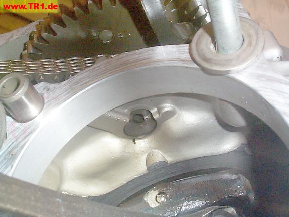
The (narrower) anti-lash gear, (thicker) camshaft gear, and cam chain sprocket are visible (left to right), viewed from above.
From this viewpoint, if the engine was operable, the visible gear teeth would be pushed towards the bottom of this image.

We’ll double-check to make sure the timing gear shaft’s oil hole is facing up to capture splashed oil.
Yup.
The shaft retainer bolt is being torqued.
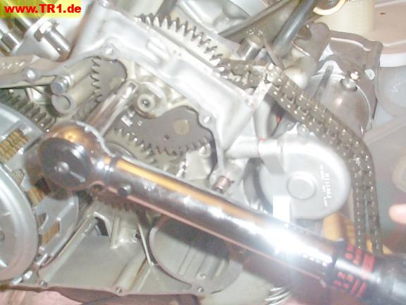
We’re done with the right-hand sidecase for now.


