We’ve already removed the heads, cylinders, pistons, and the left-hand side cover.
The engine is significantly lighter without heads or cylinders.

The right-hand sidecover is now facing us.
We’ve removed and placed the old oil filter in a disposable cup.
We’ve loosened all the right-hand sidecover hex bolts. They’re different lengths, so we’ll keep them in order during removal.

The clutch pressure plate bolts are being loosened; there’s a spring between the pressure plate and each bolt head.
The friction disc tangs are visible between the slots of the clutch housing.
It’s necessary to prevent the clutch from rotating while the clutch bolts are being loosened. We just jammed a shop rag between the clutch and primary gears. In hindsight, this is not good for the shaft bearings. Instead, we should have wrapped a strap around the clutch basket.

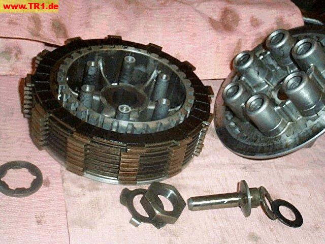
The clutch pressure plate, short clutch pushrod/bearing/washer, friction discs and clutch plates are now resting in the right side cover. The (outer) clutch housing and the (inner) clutch boss are visible.
The outer clutch housing is geared to the crankshaft primary gear. The inner clutch boss is secured to the transmission main shaft.

In operation, the crankshaft primary gear turns the outer clutch basket; the outer basket is keyed to all of the friction discs; the six springs clamp the friction discs and plates together; all of the plates are keyed to the inner basket; the inner basket is attached to transmission main shaft.
When the clutch handle is depressed, the clutch cable twists a worm drive (on the underside of the left side cover) that pushes the clutch pushrod against the clutch cover (pressure plate), compressing the six clutch springs, and releasing the clamping pressure between the clutch discs/plates, which effectively disconnects the engine from the transmission.
The inner clutch basket nut on the transmission main shaft is about to be removed. A strap prevents counterclockwise rotation of the inner clutch basket while the nut is being loosened.

First, the inner clutch boss and thrust washer were removed from the splined part of the transmission main shaft.
Next, the outer clutch housing was removed from the smooth part of the transmission main shaft.
The gear on the back of the clutch housing meshes with the large primary gear on the crankshaft.

One of the clutch plates and friction discs.
The smooth clutch plate tangs face inwards into the clutch boss; the friction disc tangs face outwards into the clutch housing.

The clutch boss with interleaved clutch plates and friction disks.
The friction discs tend to slide around if they aren’t centered by the clutch housing: the top friction disc has slipped to the left, exposing the shiny clutch plate below.
The splines on the clutch boss mate with the splines on the transmission main shaft.

Here are all the pieces to the clutch boss assembly.
The thick splined washer (left) goes between the clutch basket and clutch boss.
The lockwasher and nut hold the clutch boss to the transmission main shaft.
The short clutch pushrod, bearing race and washer sit between the transmission main shaft and the pressure plate.

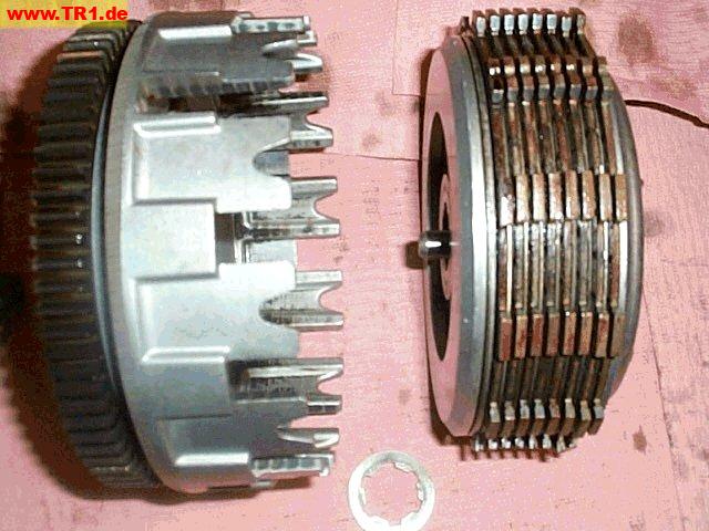
The clutch housing, thrust washer, and clutch boss with discs/plates.
The short clutch pushrod is just resting on the clutch boss splines; this part goes inside the hollow transmission main shaft.

Here’s how it looks with the clutch housing.

We’re about to remove the front camshaft gear and its chain.

The primary gear on the crankshaft is next.

We’re getting close to splitting the case halves, so the two bolts holding the starter motor onto the right case half are being removed.
From left to right, the roller bearings for the middle shaft, transmission axle shaft, transmission main shaft, and crankshaft are visible.

We’re loosening the case half hex bolts.
The driveshaft universal joint is visible; this is the rear of the engine.

Looking into the left-hand case half again.
Shifter drum is at 5 o’clock;
Oil pump is at 6 o’clock; The oil pump chain cover has been removed.
Starter motor shaft is at 9 o’clock.
The oil drain bolt/screw is visible at the bottom-left.
Since most of the guts of the engine tend to stay in the left case-half when the case is split, we elected to leave the alternator on. The strap around the alternator was to loosen the alternator nut, but we didn’t do this after all.
It appeared to us that the alternator had to be removed before removing the oil pump, but another person has reported removing his oil pump without removing his alternator.

One of the case-half hex bolts is to the left of the oil pump.
There’s an additional case half screw under the oil pump gear.

The case halves are finally separated. Cool!
The starter is still sticking up from the left case half.
The right-hand case half is nearest to you; the front of the engine is to the right.

A different perspective.
The starter is to the bottom right.

Just for fun..
Power flow from pistons to rear tire:
from the pistons
to the wrist pins,
to the connecting rods,
to the crankshaft,
to the 47-tooth primary drive gear (primary gear),
to the 78-tooth primary driven gear (clutch ring gear),
to the clutch housing damper springs,
to the clutch housing (outer clutch basket),
to the friction plates,
to the clutch plates (when the clutch lever is released),
to the clutch pressure plate,
to the clutch boss (inner clutch basket),
to the transmission main shaft (primary shaft),
to the selected transmission gears and dogs,
to the transmission drive axle (countershaft),
to the middle drive gear (on the end of the countershaft),
to the middle driven gear (big gear around the damper),
to the damper cams (for shock absorbing),
to the transmission middle drive shaft (right-angle-drive in),
to the transmission middle driven shaft (right-angle-drive out),
to the driveshaft splines,
to the driveshaft u-joints,
to the driveshaft,
to the final drive shaft (pinion gear near rear wheel),
to the ring gear,
to the clutch hub (rear wheel hub splines),
to the rear wheel hub,
to the rear tire.
(Terms from the Yamaha Motor Company Service Manual are generally given first; terms that I am most familiar with are given in parenthesis or brackets.)