Reassembly of the transmission.
The left case half.
The transmission will live between the middle gear assembly (far left) and the crankshaft assembly (far right).
The end of the middle drive shaft that’s inside the left case half (not visible – it’s under the big bearing to the left) meshes at right angles with another geared shaft that eventually turns the rear wheel driveshaft.
The huge solid metal counterweights contribute most of the weight to this assembly.

These two bearings will support the left ends of the transmission shafts; similar bearings are in other case half.
The mainshaft bearing (top), drive axle bearing (middle), and shifter fork drum (bottom) are visible.

The clutch pushrod hole (top bearing) drive axle shaft oil fitting (middle), and shifter drum (bottom) are visible.
The left-hand crankshaft counterweight is to the upper-right.

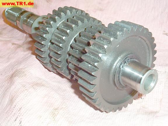
Here’s our transmission – about 10 pounds of it.
The four free gears have been slid off the axle shaft. These parts get installed in order from left to right.
The gears are 5-2-3-4-1 (from left to right); the axle shaft’s middle drive gear is at the far right.
The gears are 5-2-3-4-1 (from left to right); the axle shaft’s middle drive gear is at the far right.
Yamaha-speak:
Mainshaft (top of image) gears are called pinion gears.
Axle shaft (bottom of image) gears are called wheel gears.
There are three replacement parts in this image: shifter fork # 3 (bottom middle) and the two gears immediately to its right.

A circlip (right) prevents this 5th gear pinion from sliding off its mainshaft.
Wheel gears 2 and 3 are held onto the drive axle in a similar fashion.
This is an image of our spare mainshaft. There are certain disadvantages associated with receiving slightly oily, heavy, angular pieces of metal wrapped in what was may have once been described as newspaper after having been transported cross-country by multiple shippers. This image was made after the *first* cleaning: shreds of newspaper are no longer crushed between every gear. On the plus side: the transmission survived.
Let’s start assembling stuff.
The 5th gear wheel and fork #1 are first positioned in the left case half.

The 5th gear wheel and fork #1, resting in the left case half.
The fork’s cam follower is inserted in its slot in the shifter drum.

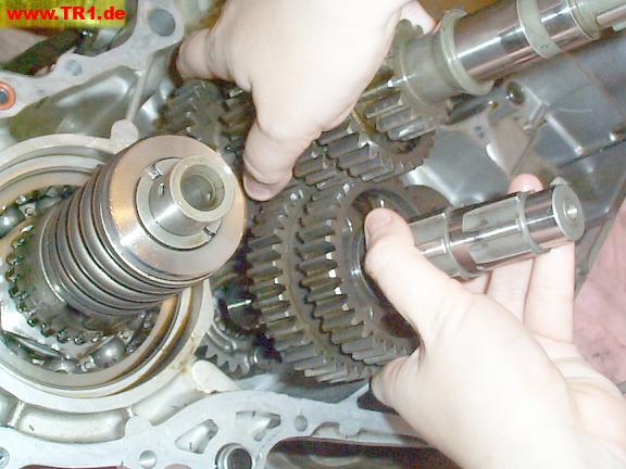
Both shafts of the transmission are about to be positioned in the left case half.
The gear we just laid in the case will reside on the leftmost splines of the drive axle (bottom left).

Because the two gears on the drive axle are surrounded by other gears on the mainshaft, both transmission shafts have to be installed at the same time.
Because we’ve also got to get the 5th gear wheel on its splined shaft, a little wiggling and turning are also required.
Both shafts seated in their bearings with a satisfyingly solid clunk.
Shifter fork # 1 is visible where we left it.

Shifter fork # 2 is added: the fork pawls are inserted between pinion gear 2/3; the fork cam follower is inserted in its cam slot in the shifter drum.
(Pinion gear 2/3 is a single piece of metal with a different gear machined on each end.)

We’ll add 4th wheel gear and its shifter fork # 3 together.
This transmission has three shifter forks: this is the last one.

It’s time to add the shifter fork shaft.
On this engine, the shaft is not symmetrical: the half-moon end must face towards the right-hand case half, and the flat must face towards the axle shaft.
The flat spot prevents the shaft from hitting the rightmost gear on the axle shaft.
The keyway on the end of the shaft prevents the flat spot from turning away from the gear.

The flat notch isn’t very deep.
There’s gotta be an interesting engineering story here.

The shifter fork shaft will go through all three forks.

It’s necessary to wiggle the lower shifter forks onto the shifter fork shaft and into the slots on the drum while sliding the shaft into position.

The shifter fork shaft has been installed.
Here’s a nice view of all three shifter fork cam followers engaged in their shifter drum slots.
The shifter forks’ cylindrical ends are called cam followers ’cause they follow the cutouts in the shifter drum cams.

View of the transmission from the right half of the engine.

View of the transmission, slightly from the rear.
The shifter fork shaft flat spot faces the axle shaft when the keyway points towards the bottom of the engine.

1st wheel gear is being added.

The last gear to install on the drive axle is the middle drive gear.
During installation, the gear rubs against the shifter fork shaft until it’s in positition opposite the shaft’s flat spot.

There’s not much clearance between the middle drive gear and the shifter fork shaft’s flat spot.

The shop rag is just visible in the gap between the middle drive gear (top gear) and the shifter fork shaft flat spot.

A view from the shifter drum side.
The drive axle shaft (left) will be supported by a bearing in the right-hand case half.

The shifter drum, fully counterclockwise at 5th speed position.
As the shifter drum is rotated, the drum’s slots slide the shifter forks on the shifter fork shaft in a particular pattern. Only one fork at a time positions its gear against an adjacent gear, locking the two gears together, and thus selecting a particular speed.
The cam (slot) positions for 1st and 2nd speed are visible.
The three cam slots start about the 6 o’clock position and proceed *clockwise*.
The two angular gaps about the 6 o’clock position that proceed *counterclockwise* serve no purpose beyond saving weight and metal.
Shifter fork cam follower #3 follows the top slot; (up for 1st, down for 3rd speed).
Shifter fork cam follower #2 follows the middle slot (up for 4th, down for 5th speed) .
Shifter fork cam follower #1 follows the bottom slot (up for 2nd speed).
Raising shifter fork # 3 (top slot) would yield 1st speed.
Raising shifter fork # 1 (bottom slot) (after shifter fork # 3 is lowered) would yield 2nd speed.

The shifter drum, fully clockwise at 1st speed.
The cam positions for 5th, 4th and 3rd speeds are visible.
The neutral switch (bottom) is off (open).
The shifter drum at the neutral position, between 1st and 2nd speed.
The neutral switch (bottom) is on (closed): the little green light would be illuminated.
The cam positions for 5th and 4th speeds are visible.

Ah! Gear appreciation time.
This is also a good time to make sure the transmission functions properly by turning the mainshaft while rotating the shifter drum through all 5 gears.
It’s cool and educational. :-)
149,1 64%
The middle gear assembly is to the left.
The very end of the middle gear shaft is visible (bottom left):
it’ll be supported in a needle-bearing race after the right-hand crankcase half is added.

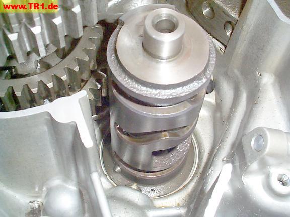
The middle gear assembly and driveshaft U-joint (universal joint) (left).
The damper assembly surrounds the middle drive gear shaft (top).
The left half of the U-joint just flops around when it’s not attached (as viewed here). When the driveshaft end is attached, the U-joint points almost straight.
Right-angle-drives are [functionally] at both ends of the driveshaft: here at the transmission, and back at the rear wheel.
Most chain-driven bikes lack right-angle drives: a chain simply connects sprockets on the rear wheel axle with sprockets on the transmission axle shaft. Chains require more frequent – and messier – maintenance, but yield somewhat more power. I prefer driveshafts.:-)

The damper assembly absorbs strong shocks to the drive train by allowing the middle gear and middle gear shaft to differ by a few degrees.
The damper spring (top) pushes the two parts of the damper cam (visible below the spring) together – really hard. If the drive train experiences a really strong jerk, the cams can rotate against one another a bit, momentarily compressing the really strong spring.
The bottom damper cam’s outside splines will mesh with the middle driven gear that will go around it.
Though it’s not visible, the upper damper cam (just below the spring) is splined to the shaft that runs through its middle.

The middle drive gear is a fairly beefy part.
The left-case-half bearing is attached; the right-case-half bearing is still in the right case half.

The inside splines (right) on this part mesh with the outside splines on the damper cam.

The gear meshes with the middle drive gear on the transmission.
The top lip (above the gear) sits inside a similar bearing in the right-hand case half.

The middle driven gear is installed around the rest of the middle gear assembly.
The orange O-ring above the driven middle gear (top edge of image) feeds unfiltered oil from the left-hand case half to the middle-driven-gear shaft and gear bearings in the right-hand case half.

The middle drive and middle driven gears are meshed together.
When the transmission drive axle shaft turns, the U-joint to the rear wheel flops around.
The transmission mainshaft will poke through the right-hand case half bearing, the transmission outer basket and the (splined) inner basket.

View of the installed transmission.
The middle driven gear is to the left, surrounding the middle drive shaft.
The middle drive gear, on the drive axle, is below it.
The mainshaft is to the right.
The shifter drum is to the bottom right, just below the shifter fork shaft.
The mainshaft is splined for the clutch boss (inner basket).

View of the left case half.
The O-ring below the crankshaft counterweight feeds a portion of the oil from the oil pump to the oil filter in the right-hand case half. Filtered oil via the right-hand case cover is then fed to both the right-hand crankshaft end for the rod big-ends (on the crankshaft), and via the external oil pipes to the camshafts (in the cylinder heads). The oil pressure relief valve is also in the right-hand case half.
The crankshaft main bearings, piston rings, cylinder walls and rod little-ends are all lubricated by splash.
There is no oil *pressure* sensor on this motorcycle – only an oil *level* sensor. This is somewhat unusual, but arguably a good idea. If cost and panel space weren’t a problem, it would be nice to have idiot lights for level, pressure, *and* an pressure gauge.)
After an oil change, the Genuine_Yamaha_Service_Manual recommends that one verifies oil pressure by loosening a cylinder head oil feed line (while the engine’s running) and observing oil seepage.
The next step will be to replace the two case half oil O-rings, spread a thin film of high-temperature instant gasket onto both crankcase lips, and torque the case halves together.

Just for fun, a side view of both rods and crankshaft counterweights.
The starter motor remains installed in the left front of the crankcase half.
These steps on the crank shaft (image top) correspond to (from bottom to top): main bearing, primary gear, camshaft timing gear, nut, and oiler nipple.
